


Suitable for wiring in fixed installations of electric and electronic components in switch gear cabinets, as well as outside switchgear cabinets if installed in a protected way.
UL/CSA Style 1007/1569
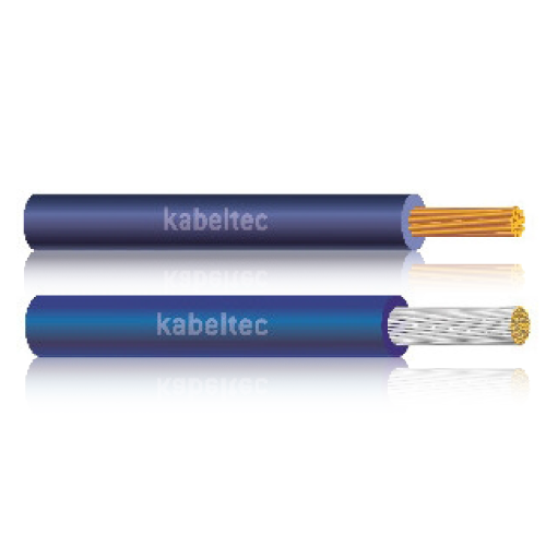
Single cores (PVC)
CONSTRUCTION:
- Strands of copper wire, bare or tinned
- PVC insulation (style 1430/1431 cross linked)
- Single core marked with type
TECHNICAL DATA:
| Conductor Material | Copper, bare or tinned |
| Conductor class | * |
| Core insulation | PVC |
| Core identification | * |
| Stranding | |
| Outer sheath | |
| Sheath colour | |
| Rated voltage [V] | 300 |
| Testing voltage [V] | 3000 |
| Conductor resistance | max. 21,8 Ohm/km at 20°C |
| Insulation resistance | min. 20 MΩ x km at 20°C |
| Current carrying capacity | |
| Min. bending radius fixed [xd] | 10 x d |
| Min. bending radius moved [xd] | 15 x d |
| Working temp fixed min/max [C] | (1007) -30°C up to +80°C (1569) -30°C up to +105 |
| Working temp moved min/mac [C] | (1007) -10°C up to +80°C (1569)-10°V up to 105°C |
| Temp at conductor max | |
| Burning behaviour |
flame retardant UL 1581 VW-1/UL2556 FV-2; CSA FT-1; self-extinguishing
|
| Approvals | UL 758-AWM |
| PART NUMBER | CORES | OUTER DIAMETER | COPPER WEIGHT KG/100M |
WEIGHT KG/100M |
|---|---|---|---|---|
| 75..0010 | 1 x 10 AWG | 4.90 | 5.16 | 6.10 |
| 75..0012 | 1 x 12 AWG | 3.90 | 3.30 | 4.00 |
| 75..0014 | 1 x 14 AWG | 3.00 | 2.00 | 2.90 |
| 75..0016 | 1 x 16 AWG | 2.50 | 1.30 | 1.85 |
| 75..0018 | 1 x 18 AWG | 2.20 | 0.82 | 1.25 |
| 75..0020 | 1 x 20 AWG | 1.90 | 0.53 | 0.85 |
| 75..0022 | 1 x 22 AWG | 1.60 | 0.34 | 0.60 |
| 75..0024 | 1 x 24 AWG | 1.40 | 0.23 | 0.43 |
| 75..0026 | 1 x 26 AWG | 1.30 | 0.16 | 0.32 |
| 75..0028 | 1 x 28 AWG | 1.20 | 0.09 | 0.29 |